
Guide
Flashback arrestor installation mistakes: ten errors that leave a gas line unprotected and how to avoid them
The commonest flashback arrestor installation mistakes are leaving it out, fitting it against the flow arrow, relying on a non-return valve alone, using a dry arrestor on wet generator gas, oil or sealant in the element, and not replacing it after a flashback. IS 11006:2011 cl 14 requires the flow direction marked on every body.
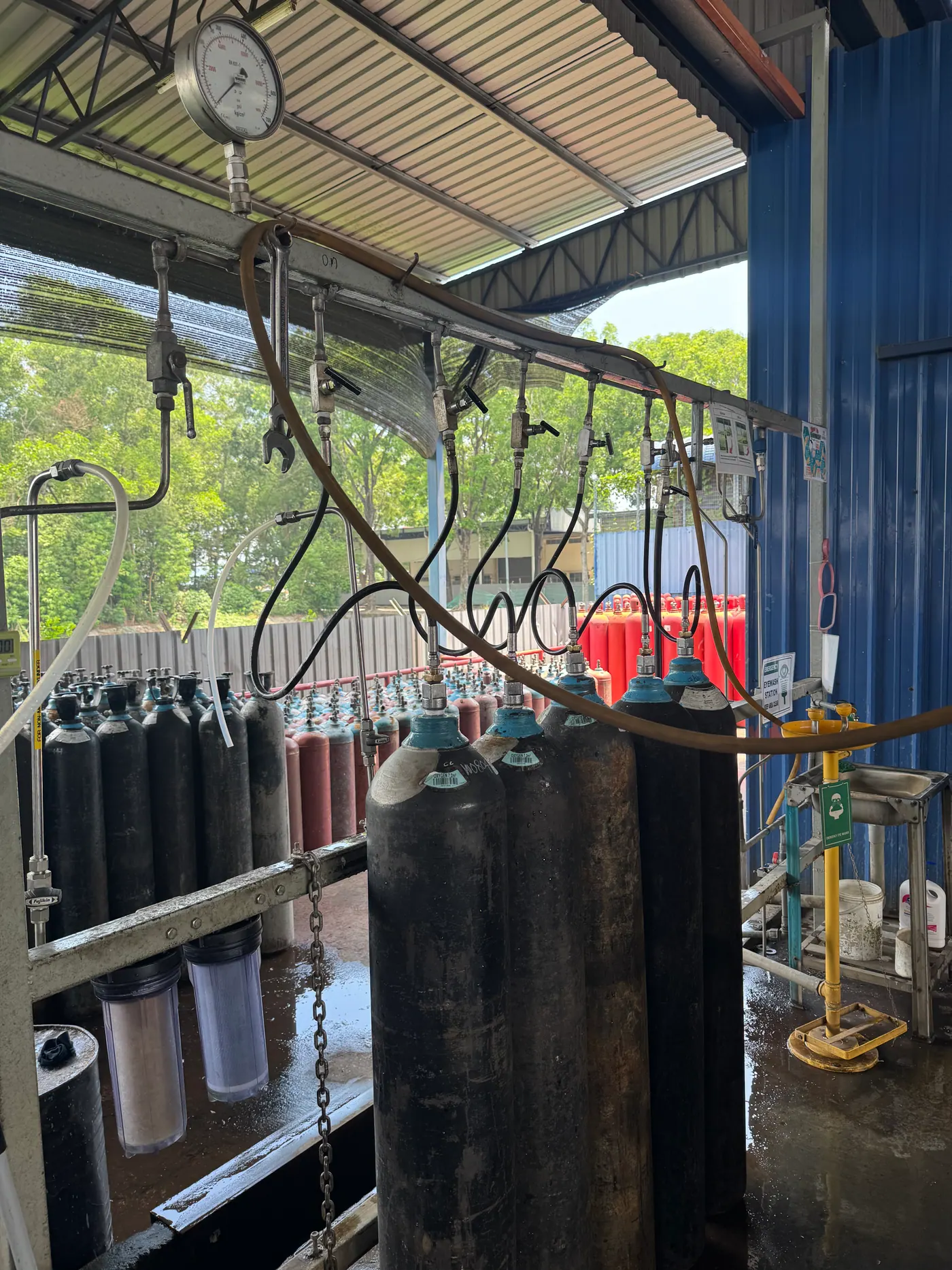
- Flow direction marking
- Every arrestor must carry the direction of nominal flow
- Placement in a cylinder supply
- Non-return valve per cylinder on the high-pressure side; one or more arrestors after the regulator
- Charging and discharging manifolds
- Three flame arrestors with non-return valves in series on each manifold
- Arrestors at pipe ends
- Do not serve any purpose at the ends; reinforcement there is still required
- Temperature cut-off after operation
- Must not be resettable; the device is replaced
Most flashback arrestors that fail in service were never given a chance to work. They were missing, fitted backwards, fitted in the wrong place, built for a different gas, choked with oil or water, or left in the line after they had already stopped a flame. The documented incidents point the same way: the dominant failure is absence or misuse, not a correctly fitted device letting a flame through. This page lists ten mistakes that recur in the standards, codes and incident reports, what each one does, and the rule that prevents it.
1. Leaving the arrestor out
The simplest mistake is the most dangerous. In an Energy Institute hot-work case study, a cutting torch lacked the arrestors it should have had, the job checklist did not require them at both the torch and the cylinder end, and trained operators did not notice they were missing. The investigation after the first fire did not fix the cause, and a similar fire followed about seven weeks later. An arrestor that is required but not fitted is invisible until the day it is needed. Check for it before every job, as part of the daily safety checklist.
2. Fitting it against the flow arrow
IS 11006:2011 cl 14.1 requires every body to be marked with the direction of nominal flow, along with the gas abbreviation (A for acetylene, O for oxygen) and the maximum operating pressure in bar. A device with a non-return valve fitted backwards normally stops the gas altogether, and the usual response on site is to remove it or swap it for a plain adaptor. A device fitted backwards that still passes gas is worse, because its non-return valve, temperature cut-off and pressure cut-off now face the wrong way. IS 11006 cl 11.5.1 tests the non-return valve in its most disadvantageous position, with gravity acting to open it, so a correctly oriented device does not depend on how it hangs.
3. Believing the device works in both directions
Some quenching elements are bidirectional by design. Stephenson's 1930 sintered arrestor (BP 363,628) was arranged so that an explosion from either direction met the outer face of the element first, and packed Raschig-ring towers of the type tested by Schmidt and Haberl in 1955 are designed to arrest explosions travelling in either direction. That is a property of the element in a purpose-built plant arrestor. A welding-line arrestor is a stack of functions, and the valves in that stack are one-way. Treat every regulator and torch arrestor as directional.
4. Fitting a non-return valve instead of an arrestor
A non-return valve stops gas flowing backwards; it does not reliably stop a flame. The American Welding Society puts it plainly in Fact Sheet 28: check valves alone will not stop a flashback. The C.P.I. said the same of dry non-return valves in 1968. Both devices are needed, in the right places. The British Acetylene Association's 1962 code for supply systems put a non-return valve between each cylinder and the header on the high-pressure side, and one or more flashback arrestors after the regulator on the low-pressure side. The non-return valve guide explains why each is there.
5. Using a device built for another gas or pressure
An arrestor is type-tested with a specific fuel-oxygen mixture: 32–35 % acetylene in oxygen for acetylene devices under IS 11006:2011 Table 2, against 13–15 % propane for LPG devices. A propane arrestor on an acetylene line has never been proved against the faster acetylene flame. An oxygen device on a fuel line, or the reverse, is equally wrong. The optional colour band under IS 11006 Annex B is red for fuel gases and blue for oxygen; the gas letter on the body is the definitive check.
6. Oil, grease, paste, paint and debris
Oil and grease have no place on an arrestor. Gas Cylinders Rules 2016 Rule 15(2) bars oil or lubricant on cylinder valves, and an oiled oxygen fitting is an ignition risk in its own right. Inside a fuel-gas element, an oil film insulates the metal from the flame and makes quenching less effective, the subject of the guide to oil, grease and arrestor elements. Thread paste, loose tape and swarf from new pipework end up on the inlet filter or in the element, raising pressure drop. Paint over the body can hide the flow arrow and gas marking that cl 14 requires to be permanent. Leak-test connections with a product made for oxy-fuel systems; an IMCA hose-fire investigation (Safety Flash 02/14) advised against soapy water or anything containing oil or grease on oxygen equipment.
7. A dry arrestor on wet generator gas
Gas straight from a carbide generator is saturated with water. The C.P.I. ruled in 1968 that dry arrestors whose packing can be affected by moisture must not be used where acetylene comes from generators unless the gas is absolutely dry, and that their pressure loss rules them out of low-pressure installations generally. Water can also block a sintered element outright (Wilhelmsen/Unitor W-66 S manual). A generator outlet takes a wet hydraulic seal, which IS 11006:2011 covers as a wet-type device.
8. Undersizing, or stacking without adding up the losses
Each arrestor costs pressure, and IS 11006:2011 cl 10.6 rates flow at a 10 % pressure drop. Two or three devices in series, each sized on its catalogue maximum, can starve a heavy cutting torch, and a starved torch backfires more readily. IS 11006 cl 13 requires the manufacturer to give an installation method that keeps total pressure drop low, and IS 15190 (Part 1):2002 cl 4.12.1.5 calls for units in parallel where one cannot carry the flow. The pressure drop and flow capacity guide works through the numbers.
9. Putting it where it cannot help
Position matters on plant and pipelines. IS 15190 (Part 2):2002 cl 6.7.4 notes that arrestors serve no purpose at the closed ends of a pipe, which must still be reinforced. IS 15190 (Part 1):2002 cl 5.4 relieves a reflection point of extra wall thickness only if an arrestor sits within the predetonation distance of it, which the standard's note puts at 2.4–16.75 m at 2.8 kg/cm² absolute in tubes wider than 35.5 mm. On a filling plant, the C.P.I. called for at least one arrestor per charging rack, between the compressor and the rack inlet, and IS 15190 (Part 2) cl 8.6 now requires three in series on every charging or discharging manifold. See dead legs and predetonation distance.
10. Leaving it in after a flashback
An arrestor that has stopped a flame has done its job once. Soot from the event fouls the element; IS 11006:2011 cl 10.5 forbids a temperature cut-off from being resettable; and Wilhelmsen/Unitor tells users that an arrestor whose cut-off and shut-off have operated "must be disposed of". A decomposition can also creep slowly through packing and re-ignite the gas beyond it, as at Griesheim, where a detonation followed twenty minutes after the explosion seemed to have been stopped; see the twenty-minute delay.
The ten mistakes at a glance
| Mistake | What goes wrong | Reference |
|---|---|---|
| Not fitted | No protection; repeat events | Energy Institute case study |
| Reversed | Gas blocked, then device removed; or valves face the wrong way | IS 11006:2011 cl 14.1 |
| Assumed bidirectional | Valves cannot act on reverse events | Stephenson BP 363,628; Schmidt and Haberl |
| Non-return valve only | Flame passes the valve | AWS Fact Sheet 28; C.P.I. 1968 |
| Wrong gas or pressure | Element not proved for the flame | IS 11006:2011 Table 2, cl 14 |
| Oil, paste, debris | Poorer quenching, higher pressure drop, oxygen fire risk | Gas Cylinders Rules 2016 r 15(2) |
| Dry device on wet gas | Packing damaged or blocked | C.P.I. 1968 |
| Undersized or stacked | Torch starved, backfire | IS 11006:2011 cl 10.6, cl 13 |
| Wrong position | Pipe end or reflection point unprotected | IS 15190 (Part 2) cl 6.7.4; (Part 1) cl 5.4 |
| Not replaced after flashback | Fouled or spent device left in line | IS 11006:2011 cl 10.5 |
Rules that matter
Rules to apply
- Fit an arrestor marked F, with the gas letter and pressure that match the line, at the regulator outlet on both fuel and oxygen, and at the torch for long hoses.
- Follow the flow arrow. If a device will not pass gas, find out why; never remove it.
- Keep oil, grease and paste off every connection; use the seal the maker specifies.
- Use wet seals on generator gas and dry arrestors on dry cylinder or compressed gas.
- Add up the pressure drop of every device in series, and go parallel where flow demands it.
- Replace any arrestor that has stopped a flame or whose cut-off has operated, and record it.
- See KIGL flash-back arrestors for models and markings.
Flashback arrestor installation mistakes — frequently asked questions
Which way round does a flashback arrestor go?
With the arrow on the body pointing in the direction of gas flow, from the supply towards the torch or consumer. IS 11006:2011 cl 14.1 makes the direction of nominal flow a compulsory marking. A reversed device either blocks the gas, tempting someone to remove it, or passes gas with its non-return and cut-off valves facing the wrong way, so they cannot act on a flashback.
Where should flashback arrestors be placed?
On a cylinder set, at the regulator outlet on both the fuel and oxygen lines, and preferably at the torch inlet as well. On a manifold, the British Acetylene Association's 1962 code puts a non-return valve on each cylinder lead and arrestors after the regulator. On pipelines, IS 15190 (Part 1):2002 cl 4.12.1.2 lists the source outlet, gasholders, boosters, branch points and each consuming unit.
Are flashback arrestors bidirectional?
The quenching element may be; the device usually is not. Some sintered designs, such as Stephenson's 1930 patent, were built so a flame from either side meets the element, and packed towers stop explosions in either direction. But the non-return valve, temperature cut-off and pressure cut-off in a modern arrestor work only with gas flowing the marked way. Treat every welding arrestor as one-directional.
Can I use PTFE tape or thread sealant on a flashback arrestor?
Follow the maker's instructions, which IS 11006:2011 cl 13 obliges them to give. Many arrestor connections seal on a metal cone or a gasket, so tape is unnecessary and its fragments can be carried into the inlet filter or element. Never use oil, grease or any paste that contains them; Gas Cylinders Rules 2016 Rule 15(2) bars oil or lubricant on valves.
Can I fit a dry flashback arrestor directly after an acetylene generator?
No, not as the generator's protection. Generator gas is wet, and the C.P.I. ruled in 1968 that dry arrestors whose packing can be affected by moisture must not be used where acetylene comes from generators unless it is absolutely dry. Their pressure loss also rules them out on most low-pressure systems. A wet hydraulic seal is the right device at a generator outlet.
Do I need to replace a flashback arrestor after a flashback?
Yes, or at least have it tested by a competent person before reuse, and replace it outright if its temperature cut-off has operated. IS 11006:2011 cl 10.5 forbids that cut-off from being resettable. Soot from an arrested flame fouls the element, and a slow decomposition can creep through packing and re-ignite gas minutes later, so isolate and wait before approaching.
Is a non-return valve enough at the torch?
No. A non-return valve stops gas flowing backwards but does not reliably stop a flame. The American Welding Society states that reverse-flow check valves alone will not stop a flashback, and the C.P.I. said dry non-return valves do not necessarily stop flashbacks. Fit a device marked F for flame arrestor, normally combined with N for the non-return function.
References
- American Welding Society, Safety and Health Fact Sheet No. 28, Flashback arrestors
- Bureau of Indian Standards. (2002). (Part 1 and Part 2):2002 Acetylene Pipelines — Code of Practice (IS 15190:2002).
- Bureau of Indian Standards. (2011). Flash Back Arrestor (Flame Arrestor) — Specification, Bureau of Indian Standards (full text) (IS 11006:2011, First Revision).
- Government of India. (2016). Gas Cylinders Rules, 2016 (G.S.R. 1081(E)). Petroleum and Explosives Safety Organisation.
- International Organization for Standardization. (2017). Gas welding equipment — Safety devices — Part 1: Devices incorporating a flame (flashback) arrestor (ISO 5175-1:2017).
Enquiries
Request a quotation
State the gas or equipment, the quantity or capacity, and your location. KIGL will confirm the grade, the cylinder or plant size, and whether the location can be served from Noonmati, or through the agent network.