
Guide
Dead legs in acetylene pipework: why a closed pipe just longer than the predetonation distance is the worst geometry
A dead leg is most dangerous in acetylene service when it is just longer than the predetonation distance, which Sargent (1957) measured in 2.5 cm pipe as 9.1 m at 3.5 atm absolute and 0.9–1.0 m at 20 atm. A detonation formed there reflects at once off the closed end.
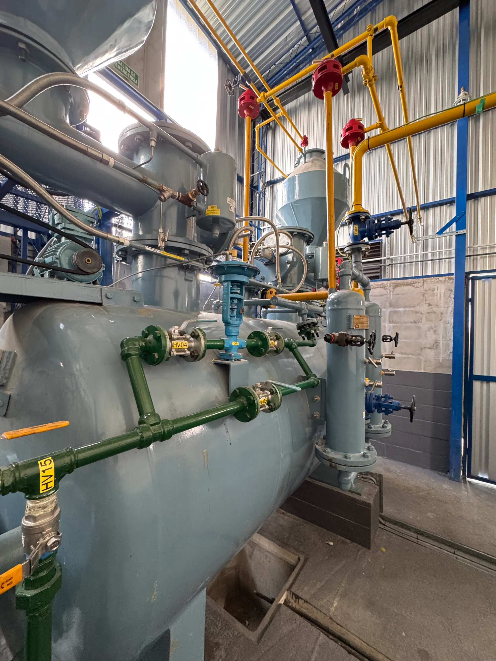
- Predetonation length in 2.5 cm pipe
- 9.1 m at 3.5 atm absolute
- Predetonation distance in narrow pipe
- 20 cm in 4 mm and 8 mm pipe at 16 atm absolute; 60 cm in 16 mm pipe at 23 atm absolute
- Pressure at a closed end
- 20
- Measured extremes
- About 300 times initial at the end of 21 m of 20 cm pipe at 1.45
- Indian rule for straight pipe length
- Straight pipe lengths chosen with reference to the predetonation distance; pipe ends reinforced to twice wall thickness whether or not arrestors are fitted
A dead leg is a branch of pipe closed at one end: a capped spare connection, an unused branch, an instrument leg, a drain line with its valve shut. In most gas service it is a nuisance because it traps condensate and air. In acetylene service it has a specific and much more serious failure mode. If its length is a little greater than the predetonation distance, a decomposition that enters it has just enough room to turn into a detonation, which then hits the closed end and reflects. That is the geometry that produces the highest pressures ever measured in acetylene pipe.
What is predetonation distance?
When decomposition starts in a pipe it usually begins as a deflagration, a flame front moving slower than sound. In a long pipe it accelerates, and after a certain length it can jump into a detonation, a supersonic front with a sudden step in pressure. The length travelled before that transition is the predetonation distance. It shortens as initial pressure rises, and it depends on bore.
Sargent's measurements in 2.5 cm pipe (paper to the International Acetylene Association, Minneapolis, 1957) are the reference set.
| Initial pressure (atm absolute) | Predetonation length in 2.5 cm pipe |
|---|---|
| 3.5 | 9.1 m |
| 3.8 | 6.7 m |
| 5.0 | 3.7 m |
| 20.0 | 0.9–1.0 m |
Below about 3.5 atm absolute, a deflagration in 2.5 cm pipe tended to die out within 4 m. In 1.9 cm pipe at 16 atm, the minimum predetonation distance was 90 cm.
Narrower pipe at higher pressure gives shorter distances still. Hölemann, Hasselmann and Dix (as compiled by S. A. Miller, 1965) measured 40 cm in 4 mm pipe at 9 atm absolute and 20 cm from 11 to 16 atm; in 8 mm pipe, 60 cm at 8.25 atm falling to 20 cm at 16–19 atm; and in 16 mm pipe, 120 cm at 21 atm and 60 cm at 23 atm. Kogarko and colleagues (Khim. Prom., 1962) found 3.5–11 m in 10 cm pipe 21 m long at 2.45–5.1 atm, again decreasing with pressure.
These distances are short compared with ordinary plant pipework. At cylinder filling pressures, a closed branch less than a metre long is already in the range where a detonation can form.
Rules that matter
The pressure figures for acetylene detonation are well established, as compiled by S. A. Miller (1965):
What happens at the closed end?
- in the detonation front, about 20–24 times the initial pressure;
- where the front meets a closed end, a reflected shock raises it another 2 to 2.5 times;
- the destructive effect in a long tube is 40–50 times the initial pressure, and it lasts longer in a long tube than in a short one.
Those are the classical figures. Measured results go far higher. Kogarko and colleagues found pressure rises of about 300 times the initial pressure at the end of 21 m of 20 cm pipe at 1.45–2.5 atm absolute. Webster et al. (IChemE Symposium Series No. 33, 1972) measured terminal pressure ratios above 320 to 1 in 12.7 mm tube, and that figure is a lower bound because it came from a bursting disc that only just failed. Their conclusion is that calculated detonation pressures have limited practical use for design: prevention and relief are the controls, not containment.
Rules that matter
The explanation is Sargent's cascading mechanism. A deflagration moves slower than sound, so the pressure of all the gas in the pipe rises ahead of the flame as it travels. When the flame finally becomes a detonation, it multiplies this already raised pressure, not the original one. The more of the pipe the deflagration has covered before transition, the higher the final pressure. This is the accepted explanation for measured rises of 100 and even 200 times.
A calculation reproduced in the compilation by S. A. Miller (1965), assuming no heat loss and a reflection factor of 2.5, puts the end-pressure ratio at about 50 times when the detonation forms at the start of the pipe, rising to about 350 times when it forms right at the end. The compilation is careful to note that the reality of cascading was still somewhat uncertain, because some Russian tests found the end pressure did not vary with the transition point. It is a strong working model, not a settled law, and it is the right basis for design.
Put the pieces together and three cases emerge for a closed branch:
Why is "just longer" the worst length?
- Shorter than the predetonation distance A decomposition entering it stays a deflagration. Pressure rises about 11 times, which pipe of the right class can be built to resist.
- Just longer than the predetonation distance The detonation forms near the end, after the deflagration has pre-compressed almost the whole branch, and reflects at once. This is the worst case.
- Much longer Detonation forms earlier in the run, and the cascading multiplier is smaller, though the reflected pressure at the end is still severe.
The compilation by S. A. Miller (1965) turns this into a design rule: avoid closed pipes whose length is not much greater than the predetonation distance. It pairs that with a vessel rule: the length-to-diameter ratio needed for detonation is about 200 at 2 atm absolute and about 10 at 15 atm absolute, so gas spaces at up to 20 atm were to be kept within about 1.2 m in length and 30 cm in diameter.
Rules that matter
IS 15190 carries the same physics into Indian practice.
What do the Indian standards require?
- IS 15190 (Part 2):2002, clause 6.7.3 relates the length of straight pipe to the predetonation distance, so that runs are not left at the critical length.
- Clause 6.7.1(a) requires pipe ends, bends, elbows, reducers, enlargers, joints and openings to be strengthened over a length of at least twice the inside diameter, to twice the pipe thickness.
- Clause 6.7.4 allows that reinforcement to be omitted at fittings where flashback arrestors with non-return valves are fitted, but keeps it at pipe ends, because arrestors serve no purpose at a closed end.
- IS 15190 (Part 1):2002, clause 5.3.2.3 treats blanked ends, valves, tees and bends of radius less than five times the bore as reflection points, needing at least twice the wall thickness over at least three bore diameters. Its Class 3 design formula uses a factor of 35 where detonation and reflection must be resisted, against 20 for undisturbed detonation. Part 1 differs from Part 2 on one point: its clause 5.4 lets the increased thickness be omitted where a flashback arrestor is located within the predetonation distance of the reflection point, whereas Part 2 clause 6.7.4 keeps reinforcement at pipe ends whatever arrestors are fitted. The two parts cover different pressure ranges (Part 1 up to 155 kPa gauge, Part 2 above); for a dead leg, the conservative course is to reinforce or remove the end.
- IS 15190 (Part 2):2002, clause 6.4 keeps high pressure pipe at DN 25 where possible and never above DN 40, which raises the pressure needed for detonation in the first place, as explained on the pipe diameter page.
The full pipeline code is summarised under IS 15190 Parts 1 and 2.
Where dead legs appear in a DA plant
In a filling plant, the usual candidates are:
- capped spare connections on charging and discharge manifolds;
- branches left in place after a manifold or drier is moved;
- pressure gauge and transmitter legs;
- drain-back and condensate lines with the valve closed;
- bypass loops around a compressor or regulator that are normally shut.
Each one should be checked against the predetonation distance for the highest pressure it can see. Dead legs cause other problems too. The C.P.I. (Safety in the Production and Use of Acetylene, Paris 1968) warned against blind corners and zones that are difficult to clear, because they hold air after purging. They collect water, which on the high pressure side can form hydrates (hydrate plugging). And they cannot be drained if they sit below the line; IS 15190 (Part 1):2002 clause 4.10 asks for a fall of about 1 mm per metre towards drain points.
Instrument legs are a special case because they cannot be removed. EIGA Doc 123/22 asks for a restrictor of 0.5 mm or a flame arrestor on pressure instruments at medium and high working pressure, and IS 15190 (Part 1):2002 clause 7.7.2(b) gives an orifice of not more than 0.1 mm² as an example of a device to limit leakage if the measuring element ruptures. A fine restriction limits flow into the leg and leakage from it; it is not by itself a flame quench at filling pressures, because the quenching diameter shrinks as pressure rises (see the flashback arrestor page), which is why EIGA offers a flame arrestor as the alternative.
Rules that matter
Rules to apply
- Remove dead legs on the high pressure side wherever possible. Cut unused branches back to the header rather than capping them at a distance.
- Where a closed branch must remain, keep it well short of the predetonation distance for the highest pressure it can see. At filling pressures, think in tens of centimetres, not metres.
- Reinforce closed ends, tees and short-radius bends to IS 15190, and do not rely on an arrestor to protect a blind end.
- Fit restrictors or arrestors on instrument legs, and use the smallest bore that will serve.
- Lay lines to fall to drains, and include every branch in the purge plan so no pocket holds air.
- Remember that a bursting disc on a dead end does not stop a detonation; the reasons are on the bursting discs vs flashback arrestors page. The same rules apply to acetylene gas pipelines of any make.
Dead legs — frequently asked questions
What is predetonation distance in acetylene pipe?
It is the distance a decomposition flame travels along a pipe, accelerating as a deflagration, before it turns into a detonation. It shortens as pressure rises; narrow pipes need a higher pressure before detonation can form at all, but at those pressures the distance is short. Sargent (1957) measured 9.1 m in 2.5 cm pipe at 3.5 atm absolute, falling to 0.9–1.0 m at 20 atm absolute.
Why are dead legs dangerous in acetylene systems?
A closed branch reflects any pressure wave that reaches its end. If the branch is a little longer than the predetonation distance, a decomposition entering it has just enough length to become a detonation, which then strikes the closed end and reflects, doubling the pressure or more. Dead legs also trap air after purging and collect condensate.
What is the cascading effect in acetylene detonation?
During a deflagration the pressure rises through the whole pipe ahead of the flame. When the flame then becomes a detonation, it multiplies this already raised pressure, so final pressures of 100 to 200 times the original have been measured. Sargent proposed the mechanism; the compilation by S. A. Miller (1965) notes its reality was still debated.
How much pressure can an acetylene detonation produce at a closed pipe end?
Classically about 40–50 times the initial pressure in a long tube, after reflection. Measured values go much higher: about 300 times in 20 cm pipe in Russian tests (Kogarko et al., 1962) and more than 320 times, as a lower bound, in the 1972 tests of Webster et al. No ordinary pipe can contain that.
What does IS 15190 say about predetonation distance?
IS 15190 (Part 2):2002 clause 6.7.3 relates the length of straight pipe to the predetonation distance. Clause 6.7.1 requires ends, bends, joints and openings to be reinforced over at least twice the bore to twice the pipe thickness, and clause 6.7.4 keeps that reinforcement at pipe ends even where arrestors are fitted.
Do flashback arrestors protect a dead leg?
Not the closed end itself. IS 15190 (Part 2):2002 clause 6.7.4 allows reinforcement at fittings to be omitted where flashback arrestors with non-return valves are provided, but states that reinforcement at pipe ends is still needed because arrestors serve no purpose there. For low-pressure lines, IS 15190 (Part 1) cl 5.4 is more permissive: no extra thickness where an arrestor sits within the predetonation distance of the reflection point. Follow the stricter rule where in doubt.
References
- Bureau of Indian Standards. (2002). (Part 1 and Part 2):2002 Acetylene Pipelines — Code of Practice (IS 15190:2002).
- Compressed Gas Association. (2009). Acetylene, incorporated by reference in US regulation (CGA G-1).
- European Industrial Gases Association. (2022). Code of Practice: Acetylene (EIGA Doc 123/22). https://www.eiga.eu/uploads/documents/DOC123.pdf
- Webster et al., The Explosive Decomposition of Acetylene in Pipelines, IChemE Symposium Series No. 33 (1972) https://www.icheme.org/media/10611/iv-paper-08.pdf
Enquiries
Request a quotation
State the gas or equipment, the quantity or capacity, and your location. KIGL will confirm the grade, the cylinder or plant size, and whether the location can be served from Noonmati, or through the agent network.