
Guide
Wet flashback arrestors: how a hydraulic seal stops a flame and how to keep the water level that makes it work
A wet flashback arrestor stops a flame by breaking the gas into bubbles rising through water, which absorbs the heat. The water level is the safety device: check it daily and after every flashback, never exceed rated delivery (the seal need only survive about 30 % over normal), and never use mercury as the seal.
- Over-delivery limit
- A hydraulic joint must not lose its seal at a delivery exceeding
- Seal liquid
- Mercury must not be used
- Level checks
- Daily
- Level access
- Liquid level must be fillable
- Generator relief
- Generators of 50 kg carbide or more need two automatic reliefs
A wet flashback arrestor stops a flame with water. Gas is led in below the surface of a water column and rises through it as bubbles; a flame travelling back from downstream has to pass through that water, and it cannot. It is the oldest arrestor design still in widespread use, it is the natural choice for the wet, low-pressure gas leaving an acetylene generator, and it has one overriding weakness: it works only while the water level is right. Everything about maintaining one follows from that.
How does a hydraulic seal stop a flame?
The principle is the same quenching physics as a sintered element, by other means. The gas stream is broken into bubbles small enough that a flame cannot propagate from one to the next, and the surrounding water absorbs heat far faster than a bubble of burning gas can generate it. Hydraulic flash arrestors had already been in use for half a century when S. A. Miller surveyed them in 1965, and the user-end hydraulic back-pressure valve he described let gas bubble through water, shed entrained water into a reservoir, and leave through a side outlet. Its relief valve was there for ordinary pressure upsets; it was not able to relieve explosion pressures. That distinction still holds: a relief valve on a wet arrestor is for process upsets, not for explosions.
What types are there?
The Commission Permanente Internationale de l'Acétylène set out the family in 1968 and noted that even the names were confused. Its terms are still the clearest:
| Device | Vents to atmosphere | Stops a flashback | Stops reverse flow | Main limitation |
|---|---|---|---|---|
| Low-pressure hydraulic valve (open type) | Yes, through a discharge pipe | Yes | Yes | Water level must be right; can be drawn into the torch if over-used |
| Submerged non-return valve (closed or high-pressure hydraulic valve) | No | Yes | Yes | Must be drained after any blowback; cannot prevent a vacuum forming above it |
| Dry non-return valve | No | Not necessarily | Yes | Not a flame barrier |
| Dry flashback arrestor | No | Yes | Not inherently | Pressure drop; must not see wet generator gas unless it is absolutely dry |
In the low-pressure hydraulic valve, the pipe bringing gas in dips deeper into the water than the discharge pipe. On a blowback of oxygen or a flashback, water is driven up both pipes; as soon as the bottom of the shorter discharge pipe is uncovered, the gas escapes outside through it, while the deeper inlet stays sealed. The discharge pipe must be long enough for its water column to hold the generator pressure, a baffle at its end recovers expelled water, and the inlet must be fitted with a water-retaining device, or set higher than the top of the discharge pipe, so the valve cannot siphon back into the generator. The C.P.I. was blunt: efficiency depends essentially on pipe arrangement, submersion depths and the quantity of water.
The submerged non-return valve has no discharge pipe, so there is no pressure compensation and the gas from a blowback stays inside. The C.P.I. made draining the valve and the hose to the torch absolutely indispensable after a blowback, because that trapped mixture could produce high pressures in a following flashback. Experience showed its real efficiency depended on how evenly the gas stream was distributed through the water, so the distribution devices need periodic inspection. Some are fitted with a bursting disc, and the body must be strong enough to withstand a flashback with the disc taken into account.
Rules that matter
Because a wet arrestor with too little water is an open pipe. EIGA Doc 239/23 lists loss of water in the flashback arrestor or water trap among the documented failure modes of generator systems. Three things lower the level without anyone noticing:
Why does the water level matter so much?
- Over-delivery. The C.P.I. required hydraulic devices to hold their seal at a delivery exceeding normal by around 30 %, and warned that above the rated delivery water can be carried out by the gas stream unnoticed.
- Blowbacks and flashbacks, which expel water through the discharge pipe.
- Standing idle, when a vessel corrodes or dries out. EIGA Doc 239/23 resets the corrosion-inspection clock after any shutdown of three months or more.
Hence the rules: check the level every day and after every blowback or flashback, examine the inside after each flashback (C.P.I. 1968), and never relight a torch until the mixture trapped between valve and torch has been purged. IS 11006:2011 cl 6.3 makes the design provide for this: the liquid level must be fillable, observable and adjustable without introducing air into the circuit, and cl 7 requires any vent pipe to be designed against choking. Mercury must never be used as the seal liquid (C.P.I. 1968). Where frost is possible, the C.P.I. allowed non-corrosive, non-foaming anti-freeze in hydraulic seals, but never in the water that reacts with the carbide.
Where does a wet arrestor sit on a generator?
At the outlet. IS 8471:2003 cl 12.8 requires the generator's flash-back arrestor to be designed, made and tested to IS 11006, cl 12.2 sets its steel sheet at not less than 2.0 mm, and cl 11.1 requires generators holding 50 kg of carbide or more to carry two automatic reliefs, one on the generating chamber and one on the hydraulic back-pressure valve. IS 15190 (Part 1):2002 cl 4.12.1.2 then asks for arrestors at the outlet of the generation plant, at the entry and exit of any gasholder, at each booster exit, at branch points and at each consuming unit. ISO 5175-1:2017 does not reach this position, because its scope begins downstream of a regulator.
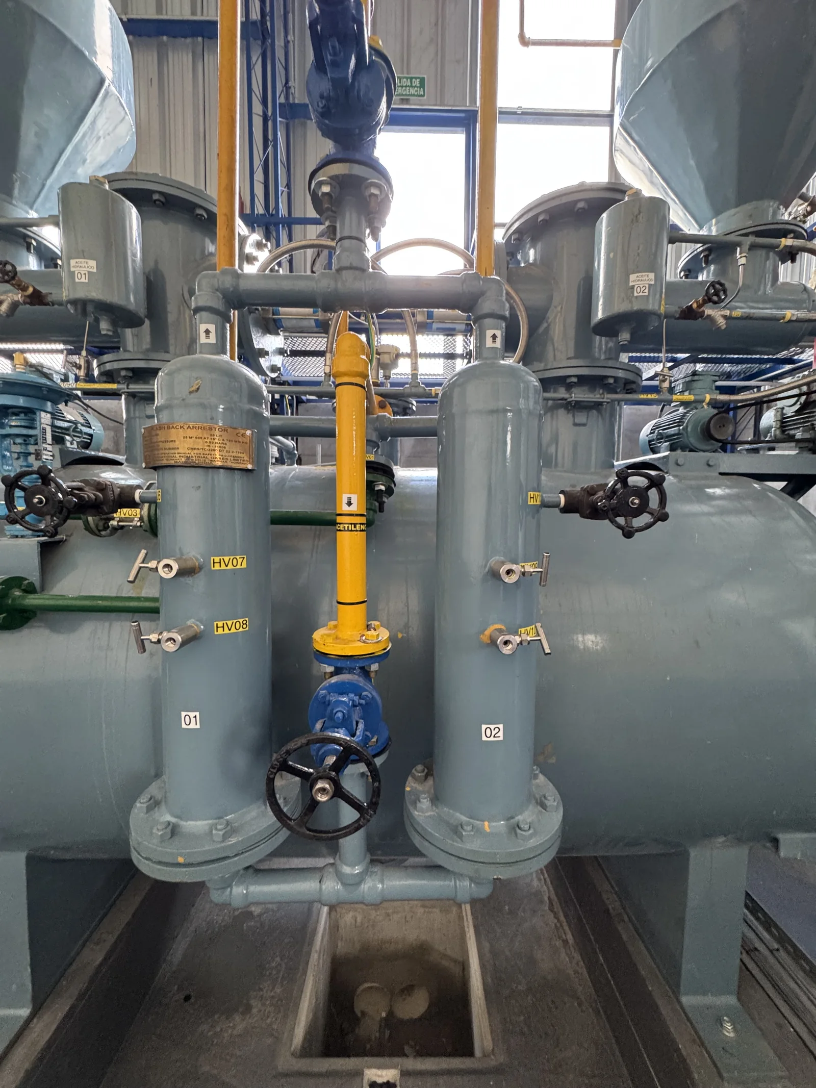
On KIGL's carbide-to-water plants, the KIGL plant operation manual places two water-filled arrestors in parallel in the generator outlet line, with non-return valves to stop gas backing into the generator, stainless-steel wire mesh and baffles inside, and a water level check valve. A safety valve on each arrestor doubles as a manual vent.
| Task (KIGL plant operation manual) | When |
|---|---|
| Check level: open the level valve slowly; if only water comes, wait for acetylene bubbles then close; if only gas comes, add water | Every time a hopper is filled |
| Drain, flush and refill, with five purge cycles to remove air | Weekly |
| Drain and clean | Annually |
| Watch the arrestor gauge: a fall of about 0.21 kg/cm²g below normal between generator and compressor indicates sludge in the line | Every shift |
Sludge is the generator-specific enemy: lime carried over from the reaction can fill the outlet pipe, the arrestors and the non-return valve, as the troubleshooting guide describes.
Rules that matter
Rules to apply
- The water level is the safety device. Check it on schedule and after every event.
- Never exceed rated delivery; size for peak flow.
- Drain a submerged non-return valve and the hose after any blowback, and purge before relighting.
- No mercury; anti-freeze only of a non-corrosive, non-foaming kind, and never in generating water.
- Specify wet arrestors to IS 11006:2011, as IS 8471 requires, not to ISO 5175-1. See generator standards and KIGL flash-back arrestors.
Wet flashback arrestors — frequently asked questions
How does a wet flashback arrestor stop a flame?
The gas enters below the water surface and rises as bubbles. A flame coming back from downstream has to travel through the water, and the bubbles are too small and the water too good a heat sink for it to survive. Hydraulic arrestors have used this principle for more than a century; the quenching physics is the same as in a sintered element.
How often should the water level in a hydraulic seal be checked?
The C.P.I. code of 1968 set it at every day and again after every oxygen blowback or flashback, with the inside examined after each flashback. On KIGL generators the operation manual asks for a level check at every hopper fill, a weekly drain and refill and an annual clean. A low level gives the gas a direct path.
What is the difference between a low-pressure hydraulic valve and a submerged non-return valve?
A low-pressure hydraulic valve has a discharge pipe open to the atmosphere, so an oxygen blowback or flashback vents outside. A submerged non-return valve has no vent, so gas pushed back stays inside and must be drained before relighting. The submerged type also cannot stop a vacuum forming above it if the torch draws more gas than the supply provides.
Can I use a dry flashback arrestor on gas straight from an acetylene generator?
Not unless the gas is completely dry. The C.P.I. warned that dry arrestors whose packing can be affected by moisture must not be used on generator gas unless it is absolutely dry, and dry elements also cost pressure that low-pressure installations cannot spare. Wet generator gas is the natural duty for a hydraulic arrestor.
Why is mercury not allowed in a hydraulic seal?
Mercury salts can form explosive acetylides, and the C.P.I. code of 1968 prohibits mercury as the liquid in hydraulic safety devices. Italy banned copper, silver and mercury and their alloys in acetylene plant outright. Use clean water, with a non-corrosive, non-foaming anti-freeze only where frost is possible.
What happens if gas flow through a wet arrestor is too high?
The gas stream can carry water out of the vessel without anyone noticing, lowering the level until the seal is lost. The C.P.I. required hydraulic devices to keep their seal at deliveries exceeding normal by around 30 %, and warned against using them above the rated delivery. Size the arrestor for peak flow, not average.
Which standard applies to a generator-outlet wet arrestor?
IS 11006:2011, which defines the wet type and covers acetylene generators and pipelines. IS 8471:2003 cl 12.8 requires the flash-back arrestor on a generator to conform to IS 11006. ISO 5175-1:2017 does not apply, because its scope begins downstream of the regulator; a generator outlet is upstream of any regulator.
References
- Bureau of Indian Standards. (2003). Acetylene Generators — Requirements (IS 8471:2003, First Revision).
- Bureau of Indian Standards. (2011). Flash Back Arrestor (Flame Arrestor) — Specification, Bureau of Indian Standards (full text) (IS 11006:2011, First Revision).
- European Industrial Gases Association. (2021). Safe Operation of Acetylene Generator Systems (EIGA Doc 237/21). https://www.eiga.eu/uploads/documents/DOC237.pdf
- European Industrial Gases Association. (2023). Mechanical Integrity of Generator Systems in Acetylene Plants (EIGA Doc 239/23). https://www.eiga.eu/uploads/documents/DOC239.pdf
Enquiries
Request a quotation
State the gas or equipment, the quantity or capacity, and your location. KIGL will confirm the grade, the cylinder or plant size, and whether the location can be served from Noonmati, or through the agent network.