
Guide
Acetylene pipelines in India under IS 15190 Part 1 (up to 155 kPa) and Part 2 (155 to 2,550 kPa): classes materials, sizing, arrestors and testing
IS 15190:2002 is India's acetylene pipeline code. Part 1 covers pipelines up to 155 kPa gauge in three classes whose permitted pressure falls as diameter rises, preferably no larger than DN 50. Part 2 covers compression and filling plant from 155 to 2,550 kPa gauge, where pipe above DN 40 is forbidden.
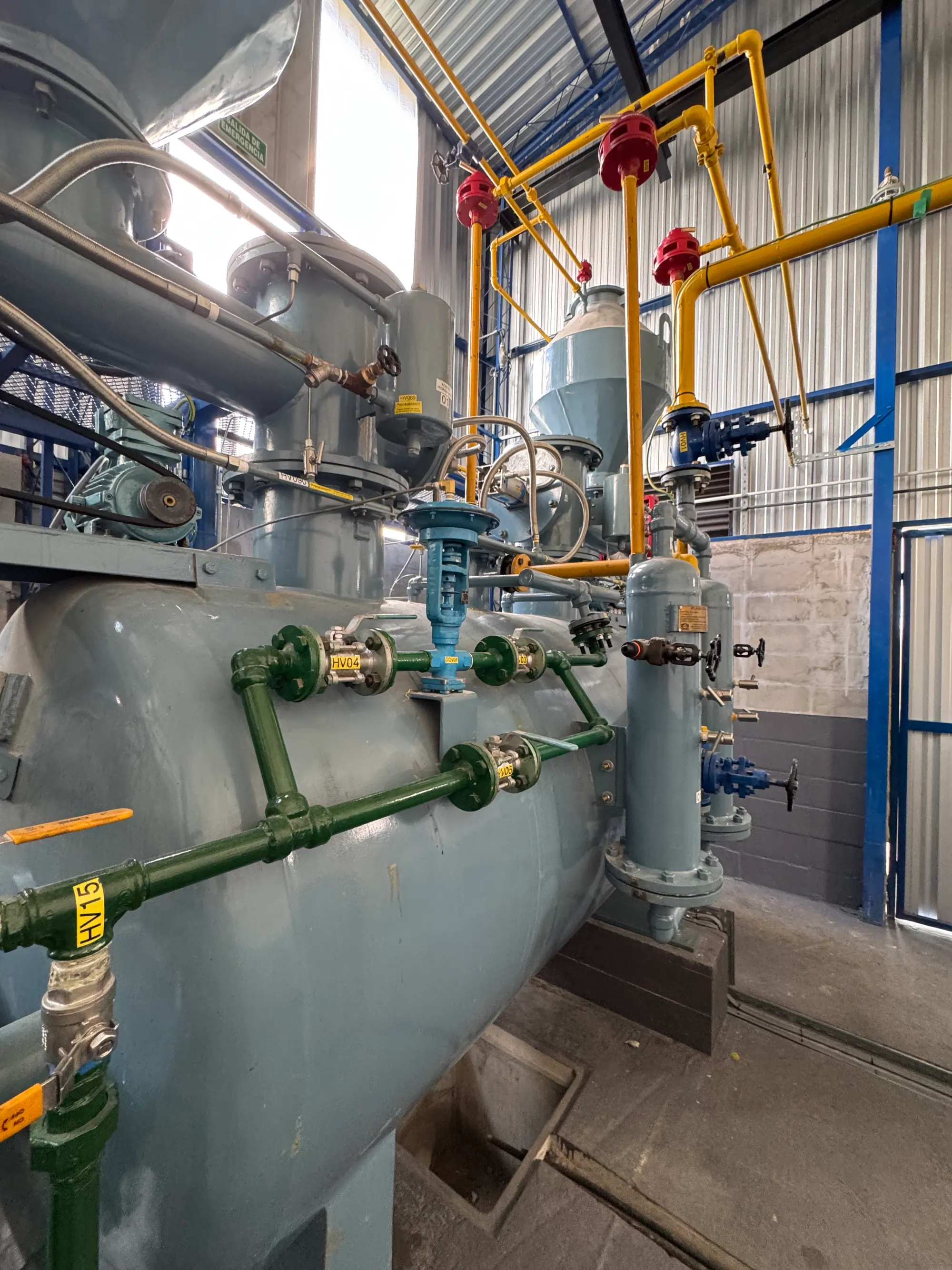
- Part 1 scope
- Working pressure up to 155 kPa g
- Diameter and pressure
- Class 1 permits 155 kPa g at DN 20 but only 50 kPa g at DN 50 and 20 kPa g at DN 80
- High-pressure pipe size
- Avoid pipe above DN 25 and never exceed DN 40; use multiple DN 25 runs for higher flow
- Copper
- Part 1: no copper alloy above 70 percent copper; Part 2: copper alloy below 65 percent; no unalloyed silver or mercury
- Hydraulic test
- Class 1: 1.5 × working pressure; Class 2: 10 ×
India's acetylene pipeline code is IS 15190, published in 2002 in two parts. Part 1 governs pipelines up to 155 kPa gauge that carry acetylene from a generator or discharge manifold to the people who use it; Part 2 governs the high-pressure side of an acetylene plant — compression, drying and the filling and discharging manifolds — from 155 to 2,550 kPa gauge. Both rest on one physical idea, the "working ranges" concept from IGC Document 9/78/E: the wider the pipe, the lower the pressure at which a decomposition can run along it, so pipe diameter and allowed pressure are set together. This page explains how each part works, with the figures, and where the printed text needs care.
Rules that matter
Part 1 applies to pipelines with a maximum working pressure of 155 kPa gauge (1.5 kg/cm² g) at temperatures up to 60 °C, carrying acetylene from calcium carbide for welding, brazing, cutting and allied processes. Pipe may be up to DN 100, but the code recommends restricting it to DN 50, and where sizing at 2 to 4 m/s calls for more than DN 50 it directs multiple DN 50 or smaller runs instead (clause 4.7). It excludes acetylene–diluent mixtures, the interconnection of the compressor with driers and filling manifolds, cylinder discharge manifolds and process-feed pipelines in chemical plant.
Table 1 is the heart of the part. It gives the maximum operating pressure, in kPa gauge, for each nominal diameter and class:
| DN, mm | Class 1 | Class 2 | Class 3 |
|---|---|---|---|
| 6–10 | 250* | — | — |
| 15 | 200* | 250* | — |
| 20 | 155 | 240* | — |
| 25 | 125 | 200* | 250* |
| 32 | 80 | 150 | 250* |
| 40 | 60 | 130 | 250* |
| 50 | 50 | 100 | 250* |
| 65 | 30 | 75 | 250* |
| 80 | 20 | 50 | 250* |
| 100 | 20 | 40 | 250* |
*Footnote to Table 1: use shall be limited to 1.5 kg/cm². Read alone, the table appears to allow 250 kPa; with its footnote it does not, and the table must always be quoted with it.
The pattern is the point. A Class 1 pipe — designed for internal pressure only — may carry 155 kPa at DN 20 but only 50 kPa at DN 50 and 20 kPa at DN 80. The experimental basis is the decomposition limit falling with diameter: Carver, Smith and Webster (IChemE Symposium Series 33, 1972) report it at about 200 kN/m² absolute in 40 mm pipe and about 100 kN/m² absolute in 250 mm pipe in Sargent's long-pipeline tests, two independent data sets agreeing. The pipe diameter and detonation page explains the mechanism.
The classes differ in what the wall is designed to hold:
Part 1 — distribution up to 155 kPa
- Class 1 — internal pressure only, medium-grade IS 1239 (Part 1) pipe, wall thickness by the ordinary Barlow-type formula with allowable stress the lesser of tensile strength over 3.0 and yield over 1.5.
- Class 2 — designed to contain a deflagration, heavy IS 1239 pipe, wall formula built on 11 times the absolute working pressure.
- Class 3 — designed for detonation, IS 1978 line pipe, 20 times absolute pressure for undisturbed detonation and 35 times where reflection is designed for. At blanked ends, valves, tees and bends tighter than 5 diameters, the wall is doubled over at least three diameters' length, unless a flashback arrestor sits within the predetonation distance of the reflection point (clauses 5.3–5.4).
Every wall gets a corrosion allowance of not less than 0.76 mm. Where a system has more than one diameter, its class is set by the widest pipe, unless flashback arrestors divide it into separate sections.
Part 1 also fixes the layout: Class 2 and 3 main headers at least 15 m from buildings, fire-water facilities, flammable-liquid storage and gasholders; overhead yard pipes with 6 m clearance over roads and rails and 10 m over tracks carrying hot material; buried pipe under at least 1.2 m of cover where loads pass; purge and relief vents at least 2 m above the roof; valves and instruments above 2 m; a gradient of about 1 mm per metre to drains sized to empty a section in 30 minutes; stop valves every 400 to 500 m on long runs; relief valves set to open at 1.1 times maximum working pressure with no isolating valve on the relief line (clauses 4.3 to 4.12).
Rules that matter
Part 2 applies to new plant compressing and filling acetylene, and to premises discharging acetylene from cylinder banks, from 155 kPa gauge (1.55 kg/cm²) to 2,550 kPa gauge. It draws on IGC 9/78/E, CGA G-1.4, NFPA 51A and UL 407, and it reads more like a plant code than a pipeline code:
Part 2 — the high-pressure plant
- the compressor or manifold building at least 15 m from public right of way and buildable boundaries, with a boundary wall or fence at least 9 m from the building (4.1.1);
- no basement or floor above or below the compressor and manifold area (4.2.1);
- a light roof or explosion venting of at least 0.06 m² per m³ of building volume (4.2.2); ventilation of at least 3.3 m³/min per m² of ceiling area at floor and roof level, through two layers of 11-mesh stainless or non-corroding gauze, brass not above 65 percent copper (4.2.3);
- heating by steam or hot water only, and boilers or flame equipment 15 m away (4.2.4–4.2.5);
- not more than 80 cylinders, or 480 m³ of gas, on manifolds under one roof without a 2.5 m high, 200 mm thick concrete dividing wall (4.2.9).
For pipe, clause 6.4 is unambiguous: avoid sizes above DN 25 and never use more than DN 40; for higher flow, run multiple DN 25 lines. Velocities are 2 to 4 m/s generally, and in compressor interconnections 10 m/s up to 6 kg/cm², 5 m/s to 11, 3 m/s to 21 and 2.5 m/s to 26 kg/cm² gauge (5.1.5). Straight runs should be shorter or longer than the predetonation distance, not just around it (6.7.3); for 2.8 kg/cm² absolute in tubes wider than 35.5 mm that distance lies between 2.4 and 16.75 m. The dead legs page explains why a closed pipe just longer than that distance is the worst geometry.
The compressor rules include a full-flow safety valve on every stage (5.1.3), a fail-safe trip on suction below 250 mm water column or discharge above the set pressure, never above 28 kg/cm² gauge, with no bypass of the switches (5.1.4), piston speed not above 0.7 m/s (5.1.9), discharge gas not above 140 °C at any stage (5.2), a 24-hour pneumatic hold losing not more than 0.2 percent per hour (5.2.3), and a back-pressure regulator after the high-pressure drier holding 14 to 17 kg/cm² gauge (5.3.1). Gauges carry bursting discs, a throttle limiting flow below 10 l/s, and red-marked maximum pressure and temperature (7.1–7.5). Each manifold has a shut-off, vent and safety valve, a flashback arrestor in the line or in each lead, three flame arrestors with non-return valves in series, leads tested to 100 kg/cm² with a 600 kg/cm² burst rating, and lead-to-manifold resistance not above 10 kΩ (8.1–8.9). Valves are rated for 210 kg/cm² and fittings for 280 kg/cm² (9.3–9.10).
Materials common to both parts
Part 1 clause 6.2.2 forbids copper and copper-bearing metal above 70 percent copper, limits silver brazing alloys to below 43 percent silver and 21 percent copper with a joint gap under 0.33 mm, and warns against aluminium, magnesium and zinc with impure acetylene. Part 2 clause 6.2 is stricter: copper alloys below 65 percent, and no unalloyed silver or mercury. Hot-finished welded pipe is not used; pipe is seamless or ERW of guaranteed joint efficiency; mitred bends and bends fabricated by cutting are banned; tees are right-angled; reducers drop at most two sizes. Welds go down in passes no thicker than 3 mm. Part 1 still calls for compressed-asbestos gaskets to IS 2712 Grade W/3; modern practice substitutes asbestos-free jointing. The copper reasoning is on the copper and acetylene page.
Flashback arrestors
Part 1 clause 4.12.1.2 requires arrestors at the outlet of the source of gas (generator or discharge manifold), at the inlet and outlet of any gasholder, at each booster exit, at every branch from main header to shop sub-header, and at the entry to each consuming unit; each ring main in a Class 3 network needs its own. Where one arrestor cannot carry the flow, several are fitted in parallel on common headers. Arrestors conform to IS 11006 — the code cites the 1984 edition; the current one is IS 11006:2011. Part 2 clause 6.7.4 adds a sharp observation: arrestors with non-return valves can replace wall reinforcement at bends and joints, but not at the closed end of a pipe, because an arrestor does nothing at a dead end.
Testing, cleaning and commissioning
| Test (Part 1 cl 10.2.7) | Class 1 | Class 2 | Class 3 |
|---|---|---|---|
| Hydraulic test pressure | 1.5 × working gauge | 10 × working, min 20 kg/cm² g | 20 × working, min 30 kg/cm² g |
| Leak test | Inert gas at ≥ working pressure, soap solution | as Class 1 | as Class 1 |
| Hold time | 30 min per 14 m³; 24 h above 68 m³ | as Class 1 | as Class 1 |
Part 2 uses 1.5 times below 155 kPa, 10 times between 155 and 250 kPa, and 20 times above 250 kPa. Pipes are blown clean with air or nitrogen at 600 to 700 kPa gauge and 12 to 20 m/s (Part 1) or 15 to 20 m/s (Part 2), purged with nitrogen of at least 97.5 percent purity at 15 to 20 m/s until the outgoing gas contains not more than 2.5 percent oxygen, held under nitrogen at about 100 kPa, and vents closed once acetylene reaches 10 percent in nitrogen. Commissioning at night is not recommended. Pipes are marked "Acetylene gas" or colour-coded to IS 2379.
Rules that matter
What this means for you
- Choose the class from the widest pipe, and keep pipe small: DN 50 or less on distribution, DN 25 on the high-pressure side.
- Read Table 1 with its 1.5 kg/cm² footnote, every time.
- Fit arrestors at source, gasholder, booster, every branch and every consumer.
- Test to the class, purge to 2.5 percent oxygen with nitrogen, and do not commission in the dark.
KIGL's acetylene gas pipelines page covers supply; the statutory side is summarised on acetylene pipeline rules.
Acetylene pipelines — frequently asked questions
What is the maximum pressure for an acetylene pipeline in India?
For distribution to consumers, IS 15190 Part 1 sets a ceiling of 155 kPa gauge (1.5 kg/cm²) at up to 60 °C, and Table 1 lowers it as the pipe gets wider. For compression, drying and filling plant, Part 2 covers 155 to 2,550 kPa gauge. Separately, IS 14814 limits free-state use at the point of consumption to 0.612 atm, or 1.021 atm with PESO clearance.
Why does the permitted pressure fall as the pipe diameter increases?
Because a decomposition flame loses heat to the wall, and a wider pipe loses proportionally less, so decomposition propagates at lower pressure. Carver, Smith and Webster (IChemE Symposium Series 33, 1972) report the limit falling from about 200 kN/m² absolute at 40 mm to about 100 kN/m² at 250 mm in Sargent's long-pipeline work. IS 15190 Table 1 builds that physics into its classes.
What are Class 1, Class 2 and Class 3 pipelines?
Class 1 is designed for internal pressure only, with medium-grade IS 1239 pipe. Class 2 is designed to contain a deflagration, using heavy IS 1239 pipe and a wall formula based on 11 times absolute pressure. Class 3 is designed for detonation, using IS 1978 line pipe and 20 or 35 times absolute pressure. Class follows the widest pipe in a section unless arrestors divide it.
Where must flashback arrestors be fitted on an acetylene pipeline?
IS 15190 Part 1 clause 4.12.1.2 requires them at the outlet of the gas source such as a generator or discharge manifold, at the inlet and outlet of any gasholder, at the exit of each booster, at each branch from main header to shop sub-header, and at the entry to each consuming unit. Part 2 adds one at each charging or discharging manifold or each lead, and three arrestors with non-return valves in series per manifold.
How is a new acetylene pipeline tested?
Hydraulically, at 1.5 times maximum working pressure for Class 1, 10 times (minimum 20 kg/cm² gauge) for Class 2 and 20 times (minimum 30 kg/cm² gauge) for Class 3, then leak-tested with inert gas at not less than working pressure by soap solution. The hold is at least 30 minutes per 14 m³ of pipe volume, and 24 hours above 68 m³.
Can I use copper or brass fittings on an acetylene line?
Not copper, and only limited brass. Part 1 forbids copper and copper-bearing metal above 70 percent copper; Part 2 requires copper alloys below 65 percent for high-pressure piping and bans unalloyed silver and mercury. Silver brazing alloys under Part 1 must have below 43 percent silver and 21 percent copper with a joint gap under 0.33 mm.
How fast should acetylene flow in a pipeline?
Both parts size pipe for 2 to 4 m/s. Where Part 1 sizing gives more than DN 50, multiple DN 50 or smaller runs are used instead. In Part 2 compressor interconnecting piping the limit falls with pressure: 10 m/s up to 6 kg/cm², 5 m/s to 11, 3 m/s to 21 and 2.5 m/s to 26 kg/cm² gauge.
References
- Bureau of Indian Standards. (2002). Acetylene Pipelines — Code of Practice, 155 to 2,550 kPa (g) (IS 15190 (Part 2):2002).
- Bureau of Indian Standards. (2002). Acetylene Pipelines — Code of Practice, up to 155 kPa (g) (IS 15190 (Part 1):2002).
- Carver, Smith and Webster, The Explosive Decomposition of Acetylene in Pipelines, IChemE Symposium Series No. 33, 1972
- European Industrial Gases Association. (n.d.). Code of Practice — Acetylene (EIGA Doc 123).
Enquiries
Request a quotation
State the gas or equipment, the quantity or capacity, and your location. KIGL will confirm the grade, the cylinder or plant size, and whether the location can be served from Noonmati, or through the agent network.