
Guide
Acetylene cylinder manifolds and bulk supply: non-return valves arrestors, draw limits and sizing
An acetylene cylinder manifold needs a non-return valve at every cylinder connection, a flashback arrestor between the manifold and the pipeline, a shut-off, vent and safety valve on the header, and enough cylinders that none supplies more than 1/7 of its contents per hour. IS 15190 (Part 2):2002 sets the Indian requirements.
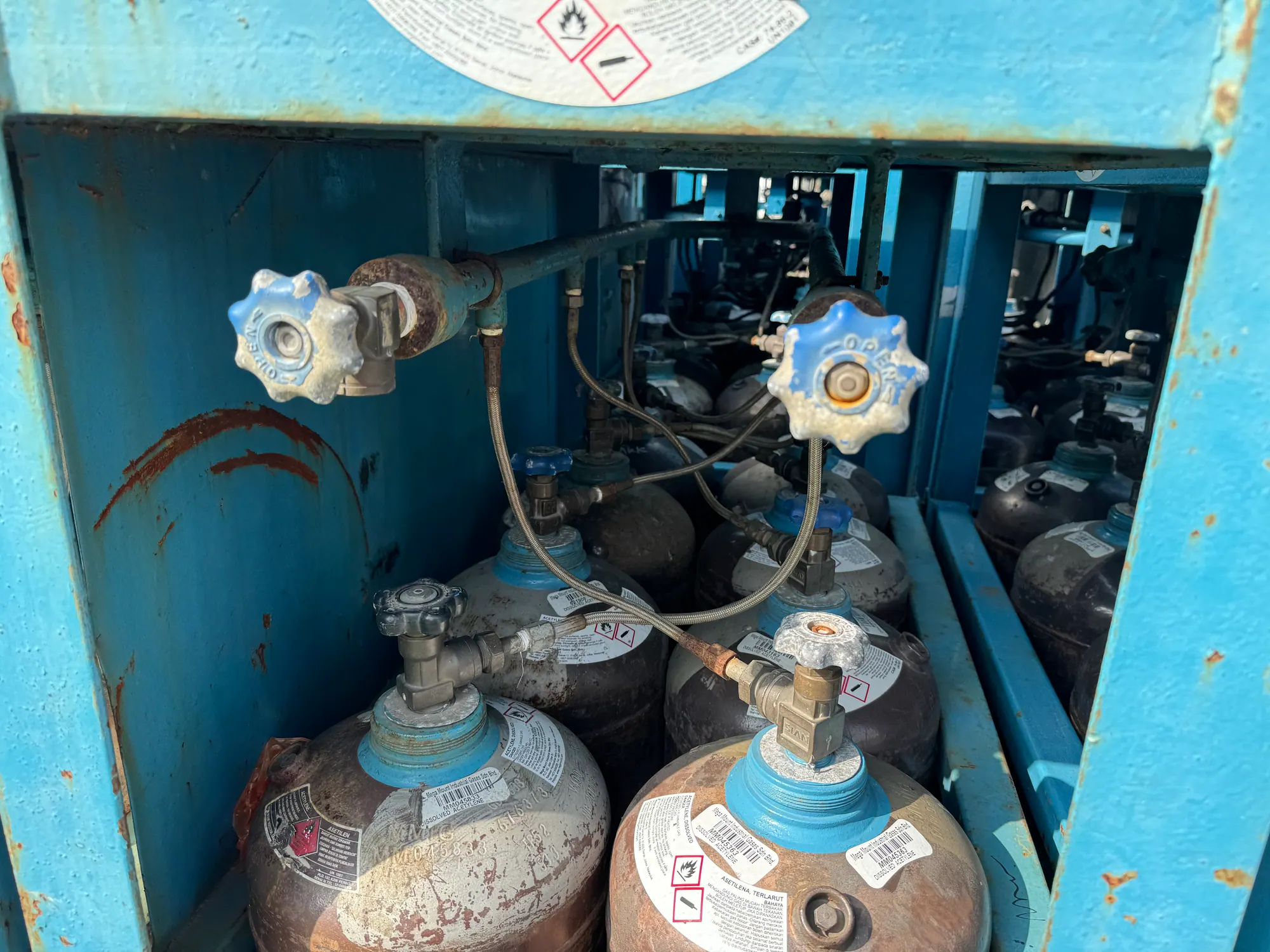
- Draw per cylinder
- Maximum 1/7 of cylinder contents per hour for welding and cutting; 1/10 intermittent solvent-sensitive; 1/15 for continuous use
- Header protection
- Each manifold provided with a shut-off valve
- Pigtails
- Minimum test pressure 9
- Cylinder spacing
- Connections spaced not less than 1.25 times the largest cylinder diameter apart
- Non-return valves
- A non-return device at every charging station; a dry non-return valve alone does not necessarily stop a flashback
A single acetylene cylinder is the right supply for a single torch of modest size. The moment a station runs a heavy cutting nozzle, or two torches share a line, or a shop wants gas at several benches from one point, the cylinder cannot keep up and the installation becomes a manifold: a header fed by several cylinders through flexible leads, with the protective devices that a shared system needs. This page sets out how to size, protect and operate one, drawing on IS 15190 (Part 2):2002, the Gas Cylinders Rules 2016, CGA G-1 and the C.P.I. 1968 safety code.
Why one cylinder is not enough
Acetylene leaves a cylinder by coming out of solution in acetone, and that is a slow and cold process. CGA G-1 limits the draw for welding and cutting to one-seventh of the cylinder's contents per hour, which KIGL also specifies, with one-tenth for intermittent solvent-sensitive use and one-fifteenth for continuous use. The 1965 engineering literature compiled by S. A. Miller recorded that a monolithic-mass cylinder would sustain 20 % of its contents per hour only until 65 to 80 % of the charge was gone, and that makers recommended a maximum of 12.5 or 14 % per hour; above such rates, cylinders must be coupled. Exceed the limit and the cylinder chills, solubility rises, the pressure sags, and liquid acetone is entrained into the regulator. The reasoning is on the one-seventh rule page and the winter version of it on the cold weather page.
A worked example makes the sizing obvious. Take a generic cylinder holding 6 kg of acetylene; at 1.09 g per litre at 20 °C that is about 5.5 cubic metres of gas. One-seventh of that is about 0.8 cubic metres per hour. A 25 mm plate cutting nozzle on the 1960 British Oxygen Company operating tables consumed about 14 cubic feet of acetylene an hour, roughly 0.4 cubic metres, so one cylinder serves it; a 100 mm nozzle at 18 cubic feet an hour, about 0.5 cubic metres, is near the limit; two such stations, or a gouging nozzle at 60 cubic feet an hour (1.7 cubic metres), need three cylinders on line. The arithmetic is simple: divide the hourly demand of every torch that can run at once by one-seventh of a cylinder's contents, and round up.
The architecture of a safe manifold
Every manifold has the same six elements, and each is there for a stated reason.
| Element | Requirement | Source |
|---|---|---|
| Cylinder leads (pigtails) | Flexible, metallic-reinforced, compatible with acetylene and acetone; test pressure 9,800 kPa gauge, burst 58,800 kPa gauge | IS 15190 (Part 2):2002 cl 8.8, 8.11 |
| Non-return valve at each cylinder | A non-return device of efficient type at each station so a cylinder cannot discharge back into the header | C.P.I. 1968, Ch. V |
| Header | Steel; shut-off valve, vent valve and safety valve on each manifold; at least 200 mm above or below the valve level | IS 15190 (Part 2):2002 cl 8.1, 8.5 |
| Regulator | Reduces cylinder pressure to the working pressure; fuel-gas connections left-hand threaded, as GCR Rule 4(3) requires for flammable-gas valve outlets; copper and copper alloys to be avoided under IS 14814 (the 70 % limit of Rule 37(v) applies to cylinder valves) | GCR 2016 Rule 4(3), Rule 37(v); IS 14814:2023 cl 7.3.4 |
| Flashback arrestor | In the pipeline at each manifold or in each pigtail; to IS 11006:2011 | IS 15190 (Part 2):2002 cl 8.2 |
| Earthing | Continuity where leads join the manifold not more than 10 kilo-ohm; hose braiding never used as the earth | IS 15190 (Part 2):2002 cl 8.9, 8.11 |
Two of these need argument, because they are the two most often left out.
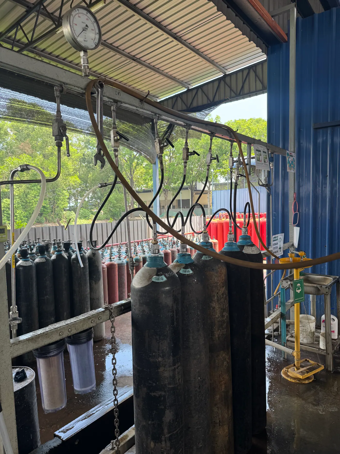
Non-return valves are not arrestors, and arrestors are not non-return valves
The C.P.I. 1968 code separated the two functions deliberately. A device to stop flashback must halt a flame before it reaches the accessories and the source upstream; if that device is not also designed to stop other gases entering, a non-return valve specially designed for the purpose must be added. And the reverse: the code states plainly that dry non-return valves do not necessarily stop flashbacks. The 1965 welding literature compiled by S. A. Miller went further, recording that a hose-protector check valve will not prevent an actual explosion travelling back if a backfire occurs when there is a mixture of oxygen and acetylene in one of the hoses.
On a manifold both failure modes exist. A cylinder at higher pressure than its neighbours, or a torch with oxygen leaking into the fuel side, can push gas backwards into the header; that is the non-return valve's job, one per cylinder. A flame that enters the header from a flashback at a torch can run the length of the shop pipework and into the cylinders; that is the arrestor's job, placed where the flow concentrates. The C.P.I. 1968 filling-plant rule required at least one flashback arrestor for every charging rack, between the compressor and the rack inlet, with an optional small individual arrestor at each station combined with the non-return device; the Indian pipeline code applies the same two-level logic to discharge manifolds. The full comparison is on non-return valve vs flashback arrestor, and the choice of device on the selection guide.
One subtlety from the C.P.I. code is worth repeating for manifold users. With dissolved acetylene drawn from a single cylinder, the porous mass itself stops a flashback and a separate arrestor is often redundant. That protection does not extend to a header or a distribution system with many branches, which holds a considerable volume of free gas, nor to any balancing vessel or distributor of its own capacity; for those, the code says the non-return and arresting devices are absolutely indispensable. A manifold is exactly such a system.
Where the arrestors go
IS 15190 (Part 1):2002 clause 4.12.1.2 lists the arrestor positions for a low-pressure acetylene network: at the outlet of the source, which for a cylinder installation is the discharge manifold rack; at the entrance and exit of any gasholder; at the exit of each booster; at the branch from the main header to each shop sub-header; and at the entry to each consuming unit. Where one unit cannot pass the flow, clause 4.12.1.5 allows units in parallel on common headers. IS 15190 (Part 2):2002 cl 8.6 goes further and calls for three flame arrestors with non-return valves in series on each cylinder charging or discharging manifold, so a discharge manifold built to that part of the code carries more than the single arrestor of cl 8.2. The arrestor after the manifold regulator is therefore the first of several, not the only one, and the torch-end arrestor at each station is the last. Sizing an arrestor to the flow without starving the torches is the subject of the pressure drop and flow capacity page.
A wet arrestor on a manifold outlet brings one more rule. The C.P.I. 1968 code requires any hydraulic device to keep its seal at a delivery exceeding, for instance, 30 % of its rated flow; over-draw it and the water is carried out with the gas, unnoticed, and the device is empty. A manifold that is enlarged by adding cylinders must have its arrestor re-rated at the same time.
Rules that matter
Operating the manifold
- Connect cylinders upright, chained, valves closed, with the key on each spindle, and open each valve slowly and not more than one and a half turns (IS 14814:2023 cl 7.3.3).
- Keep every cylinder on the header filled with the same solvent. EIGA Doc 26 (2025) forbids mixing solvent types on one manifold; an acetone cylinder and a DMF cylinder do not share a header.
- Bring a fresh bank on line before the working bank is exhausted, and change the exhausted bank with its isolation valve closed and the header vented through the vent valve to a safe place outside. Large installations run two banks so one is always in service while the other is changed, a practice already standard in 1965.
- Purge the header and leads of air after every bank change before the gas reaches a torch; pressurised acetylene admitted to closed piping that contains air can start a decomposition.
- Watch the draw. If any cylinder frosts or a regulator shows acetone, the bank is too small for the load.
- Check the electrical continuity of leads to header, the non-return valves and the arrestor on a schedule, and after any flashback.
- Protect cylinders and header from flame and overheating; the Indian code allows water spray on cylinders and manifold where the exposure justifies it.
Bundles and battery vehicles
For a user whose demand outgrows a rack of single cylinders, the next step is the bundle: a frame of cylinders permanently manifolded and filled as one unit. EIGA Doc 26 (2025) sets the filling rules, including that acetone bundles are generally filled a maximum of six times before the solvent is replenished, against about a hundred for DMF under EIGA Doc 123, and that cylinders in a bundle share one solvent. Bundles must be filled by a licensee whose Form E approval covers them and carried on a vehicle meeting Schedule VI of the Gas Cylinders Rules. Beyond bundles lies on-site generation, which has its own economics, compared on cylinder supply or on-site generation.
Rules that matter
Rules to apply
- Size the bank to one-seventh of a cylinder's contents per hour per cylinder, for the whole simultaneous demand, and round up.
- Non-return valve at every cylinder; arrestor to IS 11006 after the regulator; shut-off, vent and safety valve on the header.
- Pigtails rated to 100 kg/cm² test and 600 kg/cm² burst; the header 200 mm above or below the valves; leads earthed through the fittings, never through their braiding.
- One solvent per header; two banks for continuous work; purge after every change.
- Acetylene manifolds away from oxygen manifolds, in the open or in a ventilated room with flameproof fittings.
KIGL supplies dissolved acetylene in cylinders for racks and manifolds, manufactures flashback arrestors for the outlet, and offers acetylene pipelines for the distribution beyond.
Acetylene cylinder manifolds — frequently asked questions
When do I need a manifold instead of a single cylinder?
When your torch wants more than one-seventh of a cylinder's contents per hour. A cylinder holding 6 kg of acetylene, about 5.5 cubic metres, should supply no more than about 0.8 cubic metres per hour. A large cutting nozzle or two stations on one supply exceed that, and the cylinder frosts and spits acetone. Three cylinders on a three-way header with one regulator is the simplest manifold and cures most of these cases.
Does every cylinder on a manifold need its own non-return valve?
Yes. The C.P.I. 1968 code requires each charging station to have a non-return device so that a cylinder at higher pressure cannot discharge back through the header into another cylinder or the pipeline. The same applies in reverse on a discharge manifold. A non-return valve per pigtail also means one leaking cylinder can be closed and changed while the rest keep supplying.
Is a non-return valve the same as a flashback arrestor?
No. A non-return valve stops reverse flow; it does not reliably stop a flame. The C.P.I. 1968 code states that dry non-return valves do not necessarily stop flashbacks, and the 1965 literature compiled by S. A. Miller records that a check valve will not prevent an explosion travelling back once a mixture exists in a hose. A manifold needs both: non-return valves at the cylinders, and a flashback arrestor to IS 11006:2011 between the manifold and the pipeline.
Where exactly does the flashback arrestor go on a manifold?
IS 15190 (Part 2):2002 clause 8.2 puts one in the pipeline at each cylinder charging or discharging manifold, or in each pigtail, and IS 15190 (Part 1):2002 clause 4.12.1.2 adds arrestors at the outlet of the discharge manifold rack, at the branch from the main header to each shop sub-header, and at the entry to each consuming unit. The arrestor sits on the low-pressure side after the regulator; the high-pressure side relies on the non-return valves and small-bore pipe.
Why does the manifold pipe sit 200 mm above or below the cylinder valves?
IS 15190 (Part 2):2002 clause 8.5 requires the manifold pipe at least 200 mm above or below the level of the cylinder valves. The standard does not state the reason; in practice the offset gives each flexible lead a natural bend to take up thermal movement and cylinder-change handling without straining the valve connection, and keeps any acetone drained from the lead away from the header.
Can oxygen and acetylene manifolds share a room?
Keep them apart. The 1965 American siting rules compiled by S. A. Miller put acetylene manifolds of 3,000 cubic feet or more outside the workshop and oxygen manifolds of 6,000 cubic feet or more outside and away from any fuel-gas manifold. In India the Gas Cylinders Rules separate flammable and oxidising gases by distance or a fire-resisting partition, and IS 14814:2023 does not permit the two gases to be stored together.
What about cylinder bundles or battery vehicles?
A bundle is a set of cylinders permanently manifolded and filled as a unit. EIGA Doc 26 (2025) notes acetone bundles are generally filled a maximum of six times before the solvent is replenished, and that cylinders of different solvents must never share a manifold. Bundles need a filler licensed for them and a vehicle to Schedule VI of the Gas Cylinders Rules; for most Indian users a rack of single cylinders on a site manifold is the practical form of bulk supply.
What is the limit on manifold pressure?
On the supply side the manifold sees cylinder pressure, settled at up to 16 kgf/cm² at 15 °C under Rule 37(vi) of the Gas Cylinders Rules 2016 and higher on a hot day. After the regulator, acetylene for welding and cutting is never used above 0.612 atm without PESO clearance and never above 1.021 atm at all, per IS 14814:2023 clause 7.2.1. The pipeline downstream is designed to IS 15190 (Part 1) for that pressure.
References
- Bureau of Indian Standards. (2002). Acetylene Pipelines — Code of Practice, Part 1 for pressures up to 155 kPa (IS 15190 (Part 1):2002).
- Bureau of Indian Standards. (2002). Acetylene Pipelines — Code of Practice, Part 2 for pressures 155 kPa to 2,550 kPa (IS 15190 (Part 2):2002).
- C.P.I. (1968). Safety in the production and use of acetylene. Paris.
- Compressed Gas Association. (2009). Acetylene (CGA G-1).
- European Industrial Gases Association. (2025). Safe Filling of Acetylene Cylinders, Bundles and Battery Vehicles (EIGA Doc 26).
Enquiries
Request a quotation
State the gas or equipment, the quantity or capacity, and your location. KIGL will confirm the grade, the cylinder or plant size, and whether the location can be served from Noonmati, or through the agent network.