
Guide
IS 8471:2003 explained what the Indian Standard requires of an acetylene generator, from pressure class and water ratio to relief valves and the 2024 amendment
IS 8471:2003, with Amendment 1 of 2024, governs acetylene generators in India. It sets low (14.71 kPa) and medium (138 kPa) pressure classes, at least 8 litres of water per kg of carbide unless feed is continuous, relief capped at 152 kPa and performance at 130 percent of rated capacity.
- Pressure classes
- Low pressure 14.71 kPa g working / 32 kPa test; medium pressure 138 kPa g working
- Water-to-carbide ratio
- Not less than 8 litres of water per kilogram of carbide in a carbide-to-water generator
- Relief ceiling
- Chamber relief opens at 10 percent above working pressure or 152 kPa
- Temperature limits
- No external part above 80 °C and gas at the outlet not above 75 °C
- Flashback arrestor
- Designed
IS 8471:2003 is the Indian Standard that says what an acetylene generator must be: how strong, how hot it may run, how much water it must hold against its carbide, how it relieves, and how it is tested before it leaves the works. It is the document against which the Chief Controller of Explosives approves a generator design and the document a buyer should read before signing for a plant. This page sets out its requirements clause by clause, with the figures, and explains the one amendment issued in February 2024, which is easy to miss.
Scope and classification
The standard amalgamates the five 1977 parts of IS 8471 into one document, issued in December 2003 as a First Revision by the Gas Cylinders Sectional Committee, then designated ME 16 and now MED 16. Its foreword notes that generation of acetylene is regulated under the carbide rules, a separate instrument from the Gas Cylinders Rules; the premises are licensed by PESO as described on the PESO licence page.
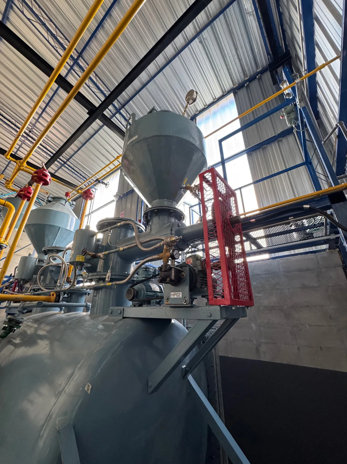
Clause 1 covers portable and stationary, automatic and non-automatic, low- and medium-pressure generators of both water-to-carbide and carbide-to-water types, for welding and cutting, cylinder filling and any other chemical process. Portable generators are limited to 3.2 m³/h and less than 20 kg carbide (1.2); stationary generators are small up to 5 m³/h and large above (1.3). KIGL's cylinder-filling plants are large, stationary, continuous, medium-pressure, carbide-to-water generators in this vocabulary.
| Class (clause 4.4.1) | Maximum working pressure, kPa g | Design pressure, kPa g | Test pressure, kPa g | Temperature, °C |
|---|---|---|---|---|
| Low pressure | 14.71 | 16.18 | 32 | 80 |
| Medium pressure | 138 | 152 | 304 | 80 |
Design pressure is 110 percent of working pressure and test pressure 200 percent of design pressure (clause 4.4). The medium-pressure ceiling of 138 kPa gauge is about 1.4 kg/cm²; a generator run at 0.92 kg/cm²g, as KIGL's manuals specify, sits inside the class with margin.
Temperature and the water ratio
Clause 4.2 sets two thermal limits, both tested at 130 percent of rated capacity and maximum pressure: no external part may exceed 80 °C, and the gas at the generator outlet may not exceed 75 °C. These are the standard's way of ensuring the reaction heat — about 429 kcal (roughly 1,800 kJ) per kg of 300 l/kg commercial carbide, as compiled by S. A. Miller (1965) from heats of formation — is carried away by water rather than accumulating in the slurry, where overheating leads to polymerisation and, in the limit, incandescence.
The water rule is clause 8.2.1: a carbide-to-water generator must hold not less than 8 litres of water for each kilogram of carbide that can be introduced into the holder, unless water and carbide are introduced continuously in a predetermined ratio. Clause 9.2 states the same ratio the other way — total carbide not more than 1 kg per 8 litres in the generating chamber — and gives 1 kg per 4 litres for the water-to-carbide type. The exemption is the operative text for a modern continuous-feed plant with automatic water control; EIGA Doc 237 clause 4.2 gives the European figure as approximately 8:1, permitted between 7:1 and 10:1. What ratio KIGL's plants run, and why temperature rather than stoichiometry decides it, is on the water-to-carbide ratio page.
Construction
Clause 8.6 gives minimum sheet thickness for the generating chamber by inside diameter: 1.25 mm up to 450 mm, 1.60 mm for 475–600 mm, 2.00 mm for 625–900 mm, 2.50 mm for 925–1,225 mm, 3.15 mm for 1,250–1,525 mm and 4.00 mm for 1,550–1,825 mm, with a shell more than 5 percent larger taking the next heavier gauge. Bottoms and dished ends are at least as thick as the shell, per IS 2825 (8.7). Carbide holders not under pressure are at least 0.8 mm steel up to 50 kg and 0.9 mm above (9.6). Where air has direct access to the gas space during charging, the carbide charge may not exceed 135 kg (9.10). A water-to-carbide charge may never fill more than 75 percent of the holder (8.1.1). The carbide feed point must be more than 250 mm above the normal water level (10.3), and on a bell-actuated feed the carbide must start feeding before the bell is within 15 cm of its landed position and stop before the top of travel (10.4).
Materials are where the 2024 amendment lands. The original clause 7.1 called for steel to IS 513 or IS 2002; Amendment No. 1 of February 2024 substitutes a list of IS 2002, IS 2062 grades E 250 A, E 250 BR, E 350 A and E 350 BR, and IS 2041 grades R 260 and R 355, and adds IS 2062:2011 and IS 2041:2009 to the reference list. Any specification or tender that still says IS 513 is out of date. Copper is prohibited in acetylene-handling parts, and copper alloys are allowed in interior parts only up to 70 percent copper (7.2); filler metal in sheet joints has the same 70 percent cap (6.2).
Relief, flashback arrestor and gasholder
| Clause | Requirement |
|---|---|
| 11.1 | Under 50 kg carbide: one relief on the hydraulic back-pressure valve. 50 kg or more: two automatic reliefs, one on the chamber and one on the back-pressure valve |
| 11.3 | Single relief passage not less than a 20 mm circle |
| 11.4 | Chamber relief opens at 10 percent above name-plate working pressure or 152 kPa, whichever is lower; recloses at not more than 15 percent below opening pressure |
| 11.5 | Water-seal relief keeps the generator below twice working pressure or 152 kPa, whichever is lower; passage not less than a 25 mm circle |
| 11.6 | No shut-off valve between relief and generator |
| 12.2 | Flashback-arrestor sheet not less than 2.0 mm; under 2.5 mm, interior heavily painted against rust |
| 12.8 | Flashback arrestor designed, manufactured and tested to IS 11006 |
| 18.4–18.7 | Gasholder bell lip at least 225 mm below water at full; 75 mm below water at relief pressure; 50 mm clearance round the bell; capacity not less than one third of the hourly rating |
| 19.2 | Pressure fluctuation not more than 10 percent up to rated capacity |
Clauses 11.4 and 11.5 are the origin of the 152 kPa (1.55 kg/cm²) figure that appears in Indian acetylene practice as the generator relief cap. IS 8471 cites IS 11006:1984; the current flashback-arrestor standard is IS 11006:2011, which requires the arrestor housing to withstand ten times its working pressure or 60 bar, whichever is higher, for five minutes. The arrestor requirements are on the flashback arrestor standards page.
Performance and testing
A generator must produce its rated capacity in continuous operation at maximum working pressure with volume fluctuation within 10 percent (5.1), and must recover not less than 90 percent of the carbide's gas yield (5.2) — a test made at the manufacturer's works for 5 m³/h or less and at the approved permanent installation for larger machines (5.3). Where a carbide-to-water generator's capacity cannot otherwise be fixed, it is rated at 62 litres per kg of carbide charged per hour, with a maximum of 125 (5.4). At 130 percent of rated capacity there must be no abnormal pressure, overheating or unsafe condition (19.3), and stopping the draw at that load must not lift the chamber relief (19.6). Each large generator has its performance test at the installation; portable and small machines are tested at the works on at least one of each type and size per year (19.7). Clause 20.1 requires a hydraulic test of every component at the table test pressure and then a pneumatic test of the assembled generator for not less than 30 minutes without leakage.
Marking and instructions
The name plate (clause 22) carries the production rating in standard m³/h, the carbide charge and size, the maker's name, the type words — Stationary or Portable, Continuous or Non-continuous, Low or Medium Pressure, Carbide-to-water or Water-to-carbide — the feed method, Automatic or Manual, and the maximum working pressure in kPa gauge. Charging, operating and maintenance instructions must be supplied with each generator (21), and the Standard Mark may be applied under licence (23). What those instructions look like in practice is covered by the operation and maintenance guide.
Reading IS 8471 against EIGA
EIGA Doc 237 covers the same machine from the operator's side. Its hard rule is that a generator may not run above 1.5 bar gauge, and that the vessel is designed for operating pressure, not for decomposition pressure, so the pressure control system is the safety barrier — a point IS 8471 makes through its relief clauses rather than in words. EIGA catalogues six generator system types operating at 0.03 to 0.5 barg (System 6 below 0.1 barg), and requires nitrogen, never carbon dioxide, for purging because of static. IS 8471 is a construction standard and is silent on purging and interlocks; those live in the manufacturer's instructions and the Form E licence conditions. A buyer should expect both: a generator built to IS 8471 and an operating manual that covers what EIGA Doc 237 covers.
Rules that matter
What this means for you
- Specify IS 8471:2003 including Amendment 1 of 2024, and the 2024 steel grades, in any tender.
- Expect two reliefs on any generator of 50 kg carbide capacity or more, set at 10 percent above working pressure and capped at 152 kPa, with no valve between them and the vessel.
- Ask for the 130 percent load test record and the 90 percent recovery figure; both are in the standard.
- Confirm the flashback arrestor is to IS 11006:2011, not the 1984 edition the standard still cites.
- Treat the 8 litre per kg water rule as a floor for batch generators and the continuous-feed exemption as the basis for automatic plants, and check the manual states the ratio it runs.
KIGL's acetylene gas plants are described on their product page; the production chemistry behind them is explained in how acetylene is made from calcium carbide.
IS 8471 — frequently asked questions
What is IS 8471 and what does it cover?
IS 8471:2003, Acetylene Generators — Requirements (First Revision), is the Indian Standard for the design, construction, performance and testing of portable and stationary, automatic and non-automatic, low- and medium-pressure generators of the water-to-carbide and carbide-to-water types, for welding and cutting, cylinder filling and chemical use. It amalgamates the five 1977 parts into one document and is maintained by the Gas Cylinders Sectional Committee MED 16. Amendment 1 was issued in February 2024.
Is 8 litres of water per kg carbide mandatory?
Clause 8.2.1 requires not less than 8 litres of water for each kilogram of carbide that can be introduced into the holder of a carbide-to-water generator, unless water and carbide are introduced continuously in a predetermined ratio. A continuous-feed generator with automatic water control therefore sits under the exemption. EIGA Doc 237 gives the European figure as about 8:1 with a permitted range of 7:1 to 10:1.
What is the difference between a low-pressure and a medium-pressure generator?
The maximum working pressure. A low-pressure generator works at up to 14.71 kPa gauge, with a design pressure of 16.18 kPa and a test pressure of 32 kPa; a medium-pressure generator at up to 138 kPa gauge (about 1.4 kg/cm²), design 152 kPa, test 304 kPa. Design pressure is 110 percent of working pressure and test pressure 200 percent of design pressure (clause 4.4). Cylinder-filling plants are medium-pressure generators.
How many relief valves does a generator need?
Clause 11.1: a generator with less than 50 kg carbide capacity may have a single relief on the hydraulic back-pressure valve; one with 50 kg or more needs two automatic reliefs, one on the generating chamber and one on the back-pressure valve. The passage area of a single relief is at least that of a 20 mm circle (11.3), a water-seal relief at least a 25 mm circle (11.5), and no shut-off valve may be fitted between relief and generator (11.6).
What performance tests does IS 8471 require?
Rated capacity at maximum working pressure with volume fluctuation within 10 percent (5.1); acetylene recovery not less than 90 percent of the carbide's yield rate (5.2), measured at the works for 5 m³/h or less and at the installation for larger plants (5.3); no abnormal pressure, overheating or unsafe condition up to 130 percent of rated capacity (19.3); and a 30-minute pneumatic leak test of the assembled generator after a hydraulic test of each component (20.1).
How much copper is allowed in a generator?
Clause 7.2 prohibits copper in acetylene-handling parts and allows copper alloys in interior parts only where the copper content does not exceed 70 percent; clause 6.2 applies the same 70 percent cap to filler metal in sheet-metal joints. This is the same threshold as Rule 37(v) of the Gas Cylinders Rules 2016 for cylinder valves.
What must the generator name plate show?
Clause 22: the acetylene production rating in standard m³/h; the amount and size of carbide per charge; the manufacturer's name and marking; the words Stationary or Portable, Continuous or Non-continuous, Low or Medium Pressure, Carbide-to-water or Water-to-carbide; the words acetylene generator; the method of carbide feed, Automatic or Manual; and the maximum working pressure in kPa gauge. Operating and maintenance instructions must accompany every generator (clause 21).
Does IS 8471 cover the whole acetylene plant?
No. It covers the generator, its carbide holders, relief devices, flashback arrestor and gasholder. The compressor, drier, purifier and filling manifold are in IS 15190 Part 2, the pipework in IS 15190 Part 1, the flashback arrestor itself in IS 11006, and the statutory licence conditions in Form E of the Gas Cylinders Rules 2016. The generator is approved by the Chief Controller of Explosives separately from the premises.
References
- Bureau of Indian Standards. (2003). Acetylene Generators — Requirements, with Amendment No. 1, February 2024 (IS 8471:2003, First Revision).
- Bureau of Indian Standards. (2011). Flash Back Arrestor (Flame Arrestor) — Specification (IS 11006:2011, First Revision).
- European Industrial Gases Association. (n.d.). Safe Operation of Acetylene Generator Systems (EIGA Doc 237).
- Petroleum and Explosives Safety Organisation. (n.d.). Petroleum and Explosives Safety Organisation. Government of India.
Enquiries
Request a quotation
State the gas or equipment, the quantity or capacity, and your location. KIGL will confirm the grade, the cylinder or plant size, and whether the location can be served from Noonmati, or through the agent network.